The final part of the lap timer build along is also the easiest part, involving only the IR Detector and an optional LED with current limiting resistors.
The previous steps can be found in the project index section of RC Arduino -
http://rcarduino.blogspot.com/p/project-index.html
A good introduction to IR Detectors is provided on the Ada Fruit website here -
http://learn.adafruit.com/ir-sensor
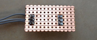
To start our build we need a small section of strip board and a set of three wires for power, ground and IR Out.
These can be soldered to the strip board so each leg of the IR Detector is connected through the copper strips of the strip board to one strand of the cable. In the picture I have used a section of ribbon cable, the cable should be long enough to suite your application, for example long enough to mount the detector on the steering column support of your Kart and allow you to attach the main unit to the steering wheel - don't make the cable longer than necessary it will only get in the way and may pick up interference.
 Notice that the IR Detector is facing away from the connecting wires and that there is room for some additional components between the detector and the connecting wires, this is to allow us to add an indicator ID.
Next we add a 10K current limiting resistor between the output of the IR Detector and the wire we will be connecting to our Arduino interrupt pin.
 For this resistor to have any effect we need to cut the copper track underneath the resistor so that the current has to pass through the resistor, a 3mm or 3.5mm drill bit will do this nicely.

Next we need to add the current limiting resistor for our indicator LED, I am using 560, but anything from 500 to 800 Ohms should be fine. This resistor connects from the row with the VCC Pin of the detector to the row below the Vout pin. From here we can also add two short lengths of connecting wire for our indicator LED, on wire should come from the VOut track and another from the track below VOut where we have just added the resistor.
This is to allow use to add an indicator LED which will light whenever the unit receives an IR Signal, this is useful as it will let you know if there is environmental interference such as reflected sunlight or fluorescent lighting.
At this point you should have the following circuit -
 You can now add an indicator LED of whatever colour will be most visible in your application. To connect the LED, the long leg should be connected to the length of wire which is soldered to the same row as the 560 Ohm resistor, the shorted leg should be connected to same the same row as the Vout pin of the IR Detector.
You can test this set up immediately by connecting 4 to 6 volts to the circuit, the positive voltage should be applied to the top row, the ground should be connected to the middle row. If you use a TV Remote or the Transponder from part 3 of the build along, you should see the LED Light, if not, try swapping the LED around incase it was soldered in reverse.
This is essentially the same circuit as shown in the Lady Ada tutorial -
http://learn.adafruit.com/ir-sensor/testing-an-ir-sensor
Assuming that you have tested your detector correctly, we can now connect it to the Lap Timer.
To do this we need to connect the Vcc wire (top pin/wire in the picture assuming the detector is facing away from the connecting wires) to the 5V supply of the Arduino. Next we need to connect the center wire to the ground of the Arduino. Finally connect the bottom wire to digital pin 2 of your Arduino.
Congratulations, you have now finished the electronics however to be able to use the lap timer you need to build a small enclosure for the detector, without this sunlight and many type of indoor lighting will saturate your detector so that it is unable to detect signals. As I am based in Dubai where the sun is always fierce I have gone as far as spraying the inside of my enclosure with ultra matt camouflage paint. You can see the enclosures I have used in the following clips of the timer in action, not that the indicator LED is on the outside of the enclosure where we can see it - you knew that already right ?
I have recently added a few extensions to the project including a count down mode and support for external audio, you can see the new menu options and see them in action at the track in the following two clips -
The external audio option uses an LM386 based amplifier to drive
external speakers. You can use this IC to add big sound to any Arduino
project, here is a link to the circuit as used in the Lap Timer -
http://rcarduino.blogspot.com/2012/08/adding-audio-to-arduino-projects.html
If you would like the latest code, contact me through the arduino forum for a zip file containing the full project.
Future Developments - I am considering adding support for three additional transponder types -
1) Magnetic - I am told that many Kart Tracks use a magnetic strip under the track which lapping Karts detect using a window sensor such as you would use for home security.
2) Commercial Beacons - The commercial beacons used at many auto racing tracks use a well know pattern of pulses, it would make sense to support this pattern allowing users to 'arrive and drive' without having to place your own transponder around the track.
3) User selected pulse length - Allow the user to choose a pulse length, this would allow two or three systems to be used alongside each other. All of the calculations needed to build your own unique transponder are linked in previous parts of build along.
Stay tuned.
Duane B
The previous steps can be found in the project index section of RC Arduino -
http://rcarduino.blogspot.com/p/project-index.html
A good introduction to IR Detectors is provided on the Ada Fruit website here -
http://learn.adafruit.com/ir-sensor
To start our build we need a small section of strip board and a set of three wires for power, ground and IR Out.
These can be soldered to the strip board so each leg of the IR Detector is connected through the copper strips of the strip board to one strand of the cable. In the picture I have used a section of ribbon cable, the cable should be long enough to suite your application, for example long enough to mount the detector on the steering column support of your Kart and allow you to attach the main unit to the steering wheel - don't make the cable longer than necessary it will only get in the way and may pick up interference.

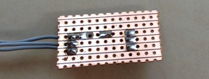
Reverse Side View

Next we add a 10K current limiting resistor between the output of the IR Detector and the wire we will be connecting to our Arduino interrupt pin.

Reverse view showing the cut in the copper track beneath the 10K resistor
Next we need to add the current limiting resistor for our indicator LED, I am using 560, but anything from 500 to 800 Ohms should be fine. This resistor connects from the row with the VCC Pin of the detector to the row below the Vout pin. From here we can also add two short lengths of connecting wire for our indicator LED, on wire should come from the VOut track and another from the track below VOut where we have just added the resistor.
This is to allow use to add an indicator LED which will light whenever the unit receives an IR Signal, this is useful as it will let you know if there is environmental interference such as reflected sunlight or fluorescent lighting.
At this point you should have the following circuit -

You can test this set up immediately by connecting 4 to 6 volts to the circuit, the positive voltage should be applied to the top row, the ground should be connected to the middle row. If you use a TV Remote or the Transponder from part 3 of the build along, you should see the LED Light, if not, try swapping the LED around incase it was soldered in reverse.
This is essentially the same circuit as shown in the Lady Ada tutorial -
http://learn.adafruit.com/ir-sensor/testing-an-ir-sensor
Assuming that you have tested your detector correctly, we can now connect it to the Lap Timer.
To do this we need to connect the Vcc wire (top pin/wire in the picture assuming the detector is facing away from the connecting wires) to the 5V supply of the Arduino. Next we need to connect the center wire to the ground of the Arduino. Finally connect the bottom wire to digital pin 2 of your Arduino.
Congratulations, you have now finished the electronics however to be able to use the lap timer you need to build a small enclosure for the detector, without this sunlight and many type of indoor lighting will saturate your detector so that it is unable to detect signals. As I am based in Dubai where the sun is always fierce I have gone as far as spraying the inside of my enclosure with ultra matt camouflage paint. You can see the enclosures I have used in the following clips of the timer in action, not that the indicator LED is on the outside of the enclosure where we can see it - you knew that already right ?
Build Along Lap Timer in action complete with IR Detector as built in this post
I have recently added a few extensions to the project including a count down mode and support for external audio, you can see the new menu options and see them in action at the track in the following two clips -
New Menu Options
|
At the track with external audio enabled
|
http://rcarduino.blogspot.com/2012/08/adding-audio-to-arduino-projects.html
If you would like the latest code, contact me through the arduino forum for a zip file containing the full project.
Future Developments - I am considering adding support for three additional transponder types -
1) Magnetic - I am told that many Kart Tracks use a magnetic strip under the track which lapping Karts detect using a window sensor such as you would use for home security.
2) Commercial Beacons - The commercial beacons used at many auto racing tracks use a well know pattern of pulses, it would make sense to support this pattern allowing users to 'arrive and drive' without having to place your own transponder around the track.
3) User selected pulse length - Allow the user to choose a pulse length, this would allow two or three systems to be used alongside each other. All of the calculations needed to build your own unique transponder are linked in previous parts of build along.
Stay tuned.
Duane B
Hello,
ReplyDeleteI've just found your blog and I have to say it is fantastic!!
I was considering doing what you are doing : creating a lap timer plus rpm sensor, etc.
Anyway, about the magnetic strip used in kart race tracks:
A reed sensor (normally open) is usually enough.
5V on one side of the reed sensor and 2 resistors on the other side of the reed sensor. One resistor to ground the input when the reed sensor is open, and the other (10Kohm) to limit the current going into the chip interrupt pin.
Oops,
ReplyDeleteI forgot the capacitor; it's necessary a capacitor in parallel in the resistor that is connected to ground, thus reducing noises caused the reed relay opening and closing.
Jorge C,
ReplyDeleteThanks for posting these responses. I knew that the magnet could be picked up using 'window sensors' which are esseantial reed sensors but have never tried it in practice so did not want to suggest something I had not tried myself - good advice on the capacitor as well. The track I used to race on was very bumpy in places, do bumps and running over the rumble strip cause false readings or are the reed sensors pretty reliable ?
Its easy enough to code around if you do get false readings, but lets see if there is a problem or not before writing solutions.
Duane B
Hi, this is a fantastic project. I am waiting for my arduino, when I have it, I will make this project.
ReplyDeleteI am very interested in can use the same arduino for 2 or 3 vehicles, making 2 or 3 transponders. Do you tried it? Do you think it's possible?
Hi, You could track two or three cars using the basic technique. I have not tried it yet but the basic approach would be to use different pulse widths for each cars transponder. As long as the detector is able to see all three cars, its should be able to detect them. The easiest way to make sure the detector can see all of the cars is to mount it at an angle somewhere above and to the side of the track.
DeleteDuane
but, even when using different pulse width in each car. How I can detect every car in arduino? Because I need to measure the time of each car.
DeleteHi, The answer is in your question - 'I need to measure the time of each car' so you need to record the last time you saw each pulse length and the next time you see a particular pulse length, you will know what the lap time was for that car. Do this for all three pulse lengths and you have the lap times for all three cars.
ReplyDeleteDuane
Hey Duane,
ReplyDeletefirst of all this is a great project, I think lots of RC drivers have been waiting for such, just as me. Thanks a lot for the effort of making this an easy build along for everybody to make. There's only one problem I have come across in the testing phase:
The transponder and IR section works fine, the status LED of the receiver lights more when IR is seen by the detector. So far so good. The arduino itself is wired as seen in the pictures of buildalong #1, the code is copied from the code you posted in the same article. I uploaded all three files to the arduino (i'm using an uno). I can start recording, but apparently neither the fake a lap button nor IR - now i connected that - can actually "produce" laps on it. Time just keeps counting without interruptions. I carefully checked the wiring several times and it all looks quite good. Do you have any idea what could be the problem?
Phil
Hi, Two things 1) The status LED Should be off altogether when there is no signal, so it looks like you have a problem in the wiring there. 2) I would suggest that you use the latest code from the downloads post, it has a few more features but - the pins are different, you will need to look at the comments in the sketch file and rewire your LCD and buttons for this code to work. Duane.
ReplyDeleteHi, It might not be a problem in your status LED Wiring, if your running older code, the status LED might be connected to something that is drawing current. I suggest that the first thing you do is download the latest code, then adjust your wiring based on the PINs used in the latest code and then let me know how you get on. Duane.
ReplyDeleteOkay, thanks for the quick help. I uploaded the latest software, changed the wiring and added a buzzer. The buzzer works nicely as I start recording. I didn't plugin the IR at first and at some random points arduino kind of generated a lap, although nothing happened. I connected the IR-detector after checking its circuit again but with the same result as before.
DeleteSo I made the same circuit as shown on the adafruit page from the link to test my sensor. Since I know the transponder is working, that should be it. It's quite awkward, at first the LED was off and lighted as I moved the transponder (so that should've been fine), after a while without changing the setup, the LED began to shine constantly. No matter if the sensor was covered or not, and even brighter than when I was testing the IR detection. Also it doesn't react to the IR anymore now, even after plugging off and on.
So my guess is that I should find a different detector.
To try the rest of the work, I'd need to know at which pin to connect the fake a lap button. It does work with the same code, right? And then will that same pin work for the IR detector as well? I tried to analyse the code, but I couldn't find anything pin related there.
Greetings
Just to make sure - your IR Detector is in a box with a very small openning ? If not, daylight, room light, all kinds of light will interfere with it.
ReplyDeleteDuane.
It is in a box indeed, today's try didn't have different results either. I also tried the box under a blanket, so there was absolutely no other light than the status LED.
DeleteMy IR-detector looks a bit different than yours but it's for 38 kHz and I made sure its pins I connected are correct, so basically it should work.
Next questions, which model of Arduino are you using ? What pin is the IR Input connected to ? and what IR Detector are you using ? Duane.
ReplyDelete1) It's an Arduino Uno.
ReplyDelete2) I wasn't sure about the respective Arduino pin (as described in my second message), so I tried the detector only in the circuit shown here https://learn.adafruit.com/ir-sensor/testing-an-ir-sensor .
Results:
first: LED almost turned off, reaction to IR is fine.
after a while: LED is constantly lightning (brighter), it doesn't seem to react to IR at all.
3) My sensor (i'll link the data sheet) is the following: https://cdn-reichelt.de/documents/datenblatt/A500/TSOP312SERIES_DATASHEET.pdf
Pin 1 of the detector needs to be connected to pin 2 of the Arduino. Duane
ReplyDeleteHello Duane !
DeleteCan you contact with me by email? I have some questions about code for Arduino.
sniz (@) tut.by
Hi, i would like to make your IR trasponder. can i have the latest code for the project? My email is s.frix@hotmail.it thank you
ReplyDeleteHello Duane !
ReplyDeleteCan you contact with me by email? I have some questions about code for Arduino.
sniz (@) tut.by
Hi Duane,
ReplyDeleteThank you for posting this project in incredible detail!
I'm an electronics technologist and my son is just getting into RC cars, so this project is a perfect fit for us! I have a few questions, if you don't mind....
Could you recommend a part # for the IR emitter and detector? It looks like you've used similar parts to: https://www.adafruit.com/product/157 and https://www.adafruit.com/product/387
Also, I was just curious how you mount it in your car? Do you have the top of the LED pointing out the side window? Thanks!